 Chinese
 English
 Russian
 Spanish
 Portuguese
Flexible PCB Design
Excellent Quality
- 100+ PCB Design & Layout projects per year
- Outstanding designers with 10+ working experiences.
- 7/24 Live sales & tech support
- 6 hours PCB Layout expedite services
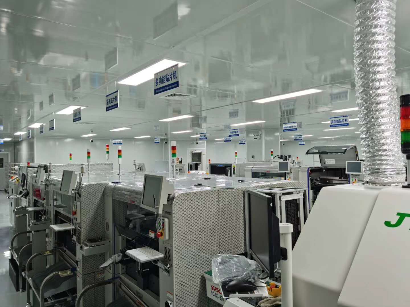
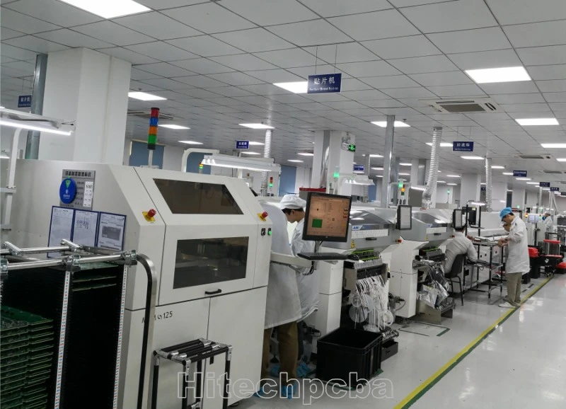
Company Show
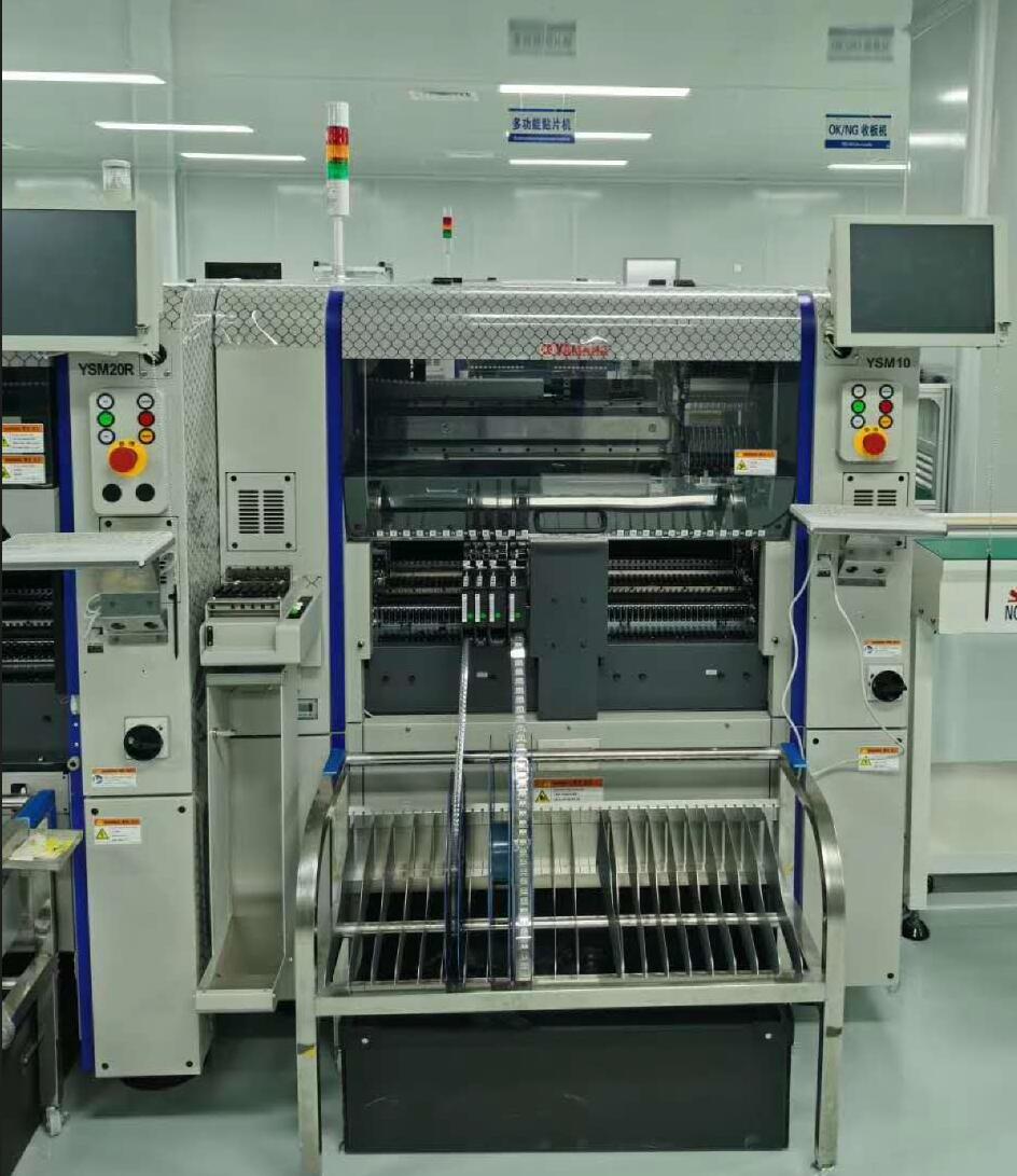

Advantages Of Our PCB Design
- Min.trace width 2.5mil,
- Min trace spacing 2.5mil,
- Min vias 6mil ( 4mil laser drilling),
- Max layer count 38 layers,
- Min BGA spacing 0.4mm,
- Max BGA Pin 2500pin,
- HDI highest Layer count 18 layers,
- Fastest delivery time 6 hours per item.

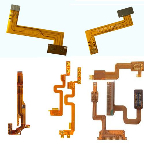
Flexible PCB Design
Design Guidelines for Flexible PCB
Printed circuit boards offer electrical connections and mechanical support to electronic components. Flexible circuit boards are usually found in modern day devices and miniaturized devices. Also, these boards offer a lot of benefits. They are suitable for designing tiny cables and very lightweight circuits.
Flex PCBs also known as flexible circuits enable circuitry to fit into any electronic product. Also, these circuit boards have a unique patterned circuitry and component arrangement. If you are looking forward to designing your flexible PCBs yourself, this article is for you
What is Flex PCB?
Flexible printed circuits, also known as flex circuits, are sometimes regarded as a printed circuit board (PCB) that can bend, when in reality there are significant differences between PCB’s and flex circuits when it comes to design, fabrication and functionality. One common mistake that designers make is to design a flexible circuit using the same rules as a PCB. Flex circuits require a unique set-up and have their own set of design rules that the Hitechpcb team has termed “flex-izing” and have worked hard to perfect over the last many years.
Flexible PCB, which also called Flex PCB, Flexible circuit board or flex circuit, it consists of PI base material, adhesive layer, copper layer, coverlay and sometimes with stiffeners. Flexible PCBs are now being used widely to replace traditional FR4 PCB in various different applications due to the benefits from flex PCB specially. Although more expensive than a normal rigid PCB, the right design in the right application could save weight and time in assembly, coupled with the reliability which makes flexible circuit board a worthwhile consideration.
A flexible printed circuit consists of a metallic layer of traces, usually copper, bonded to a dielectric layer, usually polyimide. Thickness of the metal layer can be very thin (<.0001″) to very thick (> .010″) and the dielectric thickness can vary from .0005″ to .010″. Often an adhesive is used to bond the metal to the substrate, but other types of bonding such as vapor deposition can be used to attach the metal.
How to calculate your flex pcb bend radius?
Because copper tends to readily oxidize, the exposed surfaces are often covered with a protective layer, gold or solder are the two most common materials because of their conductivity and environmental durability. For non-contact areas a dielectric material is used to protect the circuitry from oxidation or electrical shorting.
The number of material combinations that could go into a flexible printed circuit are nearly endless; current, capacitance, chemical and mechanical resistance, temperature extremes and type of flexing are just some of the criteria that impacts the material selections that best meet the functional needs. An experienced All Flex design engineer takes the critical requirements into consideration when designing a circuit to meet your needs.
Flexible printed circuit boards (FPC) has become a common component of electronic products due to its lightness and flexibility performance. It is widely used in smart terminal, wearable electronics, consumer, automotive, industrial and medical fields. The miniaturization and integrated function of electronics product development is driving FPC to fine line and multilayer design.
What is Multilayer flex PCB?
This type of flexible printed wiring boards are multilayered (with three or more conductor layers) and require plated-through holes. We could use through vias, buried vias and blind vias.
A multi layer flex circuit combine several single-sided or double-sided circuits with complex interconnections, shielding and/or surface mounted technologies in a multi layer design. The multi layers may or may not be continuously laminated together throughout the production process. If your design needs require maximum flexibility, continuous lamination may not be appropriate. Multi layer circuits are an effective solution when confronted with design challenges such as: unavoidable crossovers, specific impedance requirements, elimination of crosstalk, additional shielding and high component density. You can also link here to learn more about flex pcb bending radius.

What is a DIY Flex PCB?
A DIY flex PCB is a flex circuit you design on your own. It is now very easy to print flexible circuits on your own. The DIY method is a low cost option for designing your own flexible circuits. Over the years, technology has developed. Digitally printed flexible boards are now a reality and flexible PCBs are now an affordable alternative for both professionals and hobbyists.
DIY boards provide predictable conductivity and repeatable quality. These boards can be crucial in scaling to large production. Flexible circuits can flex to fit, thereby conforming to a particular curved design. PCB designers can shape these circuits into very complex forms.
Furthermore, flex PCBs comprise copper coated film. The copper coated film serves as the substrate of the PCB. This copper film is flexible and very easy to bend. Also, copper traces conduct signals on the flex PCB surface. There are different types of flex PCBs. A multilayer flex board features several layers of flexible copper sheet while a double layer flex board comprises double layer of copper sheet. The copper sheet is a core material in a flex board.
Equipment needed for DIY Flexible Circuit Board
When designing your flex board, you will need these pieces of equipment.
Solid ink printer
PCB design software like Proteus or Eagle
Polyimide film
Heating element
Etching chemicals
Pyralux copper lamination sheets
Solid ink printer
A4 paper
Multimeter
A laptop
Steps in Designing DIY Flexible PCB
Organize your equipment
Organization of all the equipment needed in your design process is very crucial. Ensure all your tools are in order. Also, be sure these pieces of equipment are functional.
Have your copper-coated film
You need slim sheets of polyimide having copper on one or two sides. Polyimide has a high level of melting temperature. Also, this material is sometimes referred to as Kapton. DuPont is a common type of polyimide coated with copper.
In addition, pyralux sheets are available in various polyimide thickness, adhesive thickness, and copper thickness. The adhesive holds the copper sheet and polyimide together. The Pyralux LF7062 features 1 mil Kapton, ½ mill adhesive, and ½ oz Cu. This is ideal for a printer to handle. Also, the pyralux LF9120 features 2 mil Kapton, 1 mil adhesive, and 1 oz Cu.
There are other options like double sided copper and a roughened surface. The letter R denotes the roughened surface at the end of the part number. Also, this option is applicable. However, it can be a difficult task to feed the printer with Pryalux featuring thicker copper.
Make use of a solid-ink printer
You need to use a solid ink printer. A solid ink printer helps to print on the copper film. Also, this printer doesn’t depend on charging the paper surface. You can easily replace the solid ink printer with a toner transfer iron method. However, a solid ink printer is a good choice.
Print on the Pyralux
Ensure you draw a design and use a manual feed to print on your Pyralux sheet. Most times, people use black, however, there are other colors like green, cyan, and more. Also, red seems to work fine. Avoid using light shades having tiny dots. Also, use “photo” or “high-resolution” mode whenever you are printing. This is because high resolution mode promotes more adhesion of wax.
Copper Etching
Here, you will need to dip the printed sheet into a copper etchant known as ferric chloride. Dipping will last for at least 5 minutes. Also, don’t allow the etchant to come in contact with your skin and eye. The copper thickness, temperature, and other conditions will determine the etch time. Also, this may take about 25 minutes. Therefore, check if the copper areas have dissolved and try to observe the polyimide film.
The copper etching process can be faster if you use an aquarium pump to bubble and allow heating to be about 40 degrees Celsius. Use warm water and ScotchBrite pad to scrub off the leftover wax. Alternatively, use isopropyl alcohol. However, this can take more time and effort.
Arrange and inspect
Use AVO Meter or multimeter to clean and inspect the board. Also, cleaning the board is very important as it helps you get rid of any debris on the board.
Populate the Circuit Board
It is time to cut the flex PCB in small circuits and solder. Also, you can make this process easier by taping the PCB on a piece of metal to hold it firm while working on it. You can also make use of “Tinnit” plating solution for easy soldering.
Benefits of Flex PCBs
Flexible PCBs offer a lot of benefits in several applications. These boards offer you unparalleled freedom of packaging while ensuring high density.
Ease of assembly
Flex PCBs can only fit in one way. Also, the manufacturing error rates and time is low compared to traditional wiring. With flex PCBs, you don’t need to wrap bundles of wire.
Space saving
One of the main advantages of flexible boards is that they consume less space. Therefore, this enables high density and miniaturization of electronic devices.
High reliability
The availability of connectors, fewer interconnects, and solder joint, there is less failure. Therefore, this helps to enhance reliability.
High vibration resistance
The ductility and low mass of a flexible circuit will minimize impact when under high acceleration or vibration. In contrast, a higher vibrational mass of a PCB will enhance stresses on the circuit and its components.
Thermal management
One great benefit of flex circuit is its ability to dissipate heat at a faster rate. This board doesn’t easily react to changes in temperature. Therefore, it is ideal for use in high temperature environments.
Design Rules for Flex Circuit
Flex PCBs usually comprise copper coated polyimide film. The copper coated polyimide film is the substrate of a flex PCB. Also, this film doesn’t get soft when it passes through heat. However, it remains flexible after the thermosetting process. The copper coated polyimide film is a high-quality in flex circuit board fabrication. When designing a flexible circuit, there are important rules you should know.
Understand the bending strength of your PCB
To achieve a good flex PCB design, it is crucial you know the number of times your circuit board will bend. The copper on the PCB will start cracking or stretching if a flex board bends more than it can. Also, it is advisable to identify the bent radius at the early phase of the design process. Bend radius is simply the bendiness for the flex area in the PCB.
Know your materials
The adhesive based material and adhesiveless material are the two types of flex board materials. Using adhesives at the rigid areas may form cracks in the copper plating within the holes since acrylic adhesives can soften when heated. It is advisable to integrate teardrops and anchors when designing for adhesive based flex board. DuPont Pyralux FR, Dupont Pyralux AP, and Dupont Pyralux LF are ideal materials for your flex board.
Optimize stack up
Before you start designing, ask your manufacturer for a stack up. It is important you know the stack up you will be designing. Have a meeting with your supplier to ensure you both are in agreement as regards your design.
Watch flex trace routing
The layout of your circuitry breaks or makes the circuit board. As regards the bend radius, it is advisable to use a large radius as this enhances the reliability of the PCB.
Flexible PCB is also called flexible circuits, FPC, Flex PCB. It is a kind of technology used for assembling electronic circuit by mounting electronic devices over flexible plastic layers or coverings. The coverings are either polyimide or PEEK. Besides flex circuits can be printed over silver screen made up of polyester. Flex circuits are manufactured using identical components of printed circuit boards (PCB), therefore they are called flex PCB. They are widely used in the following technologies.
Smartphones
Flex PCBs are part of signal connection for rotating and other bending parts in smartphones. For example, folding screen phone are now available in the smartphone market. Samsung, Huawei, and Royole technology released folding full screen phone between 2018 and 2019. Flex circuits are more ideal for electronic devices integrating flexible screens due to their bendable characteristics.
Automotive electronics
Flex circuit boards offer a high level of reliability. Also, these boards feature durability characteristics and heat resistance. All these properties are ideal for automotive electronic components. You will find flex circuits in LED car lights, navigation, sensors, car display, and more. There is more demand for flexible PCBs as the automotive industry continues to experience development and innovation.
Medical wearable devices
These devices are widely used in diagnosis and personal health care. They are usually attached to people’s bodies; hence, they must be unobtrusive and comfortable. Therefore, these devices need to have a compact package and dense layouts. Flex PCB contributes to the compactness and complexity of medical devices. These boards enable the manufacturing of lighter and smaller medical devices due to their high circuit density and flexibility.
Computers
The flexible copper sheets in flex boards are responsible for the flexibility they offer. Flex circuit boards are widely used in manufacturing some parts of computers. For instance, the flexible keyboard features flex circuits. Also, flex PCBs are available in personal computers, laptops, and more.
Conclusion
A flex printed circuit board offers a lot of advantages. You can fabricate your own flexible board if you adhere to the design and manufacturing rules. In this article, we have provided a step-by-step process of making a DIY flex board.

0086-755-29970700
sales@hitechpcb.com; sales@hitechcircuits.com
2F, Building C, Suojia Technology Park, Hangcheng, Bao’an, Shenzhen, Guangdong, China 518126


