Rogers PCB
What is Rogers PCB?
Rogers PCB is a type of printed circuit board (PCB) material made from a combination of epoxy and ceramic. It is well known for its high dielectric constant, low loss tangent, and high thermal conductivity, making it an ideal material for high-frequency applications. It is used in a wide range of electronics, such as:
5G Station
Cellular Base Station Antennas and Power Amplifiers
Automotive Radar and Sensors
Microwave point to point (P2P) links
LNB’s for Direct Broadcast Satellites
Microwave equipment of all kinds.
RF Identification (RFID) Tags
Rogers PCB is produced using the raw materials of the Rogers Company. Rogers company manufactures the laminate materials that are often used for manufacturing circuit boards. The Rogers PCB is a type of high-frequency PCB board, quite different from the traditional PCB board materials, epoxy resin. It uses the ceramic base as the material of high frequency. The major advantage of Rogers PCB is the temperature stability and superior dielectric constant.
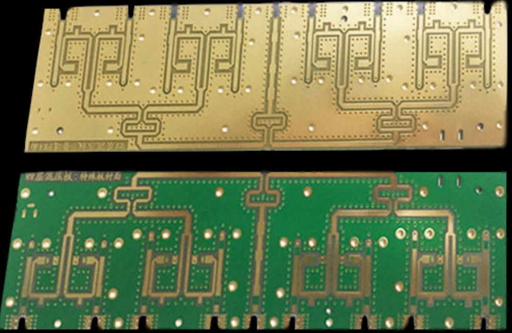
Rogers PCB has a major application in high-speed electronic designs, radio frequency applications, and commercial microwaves. The low water absorption capacity of this Rogers PCB is ideal for the application of high humidity. Other Rogers PCB applications include RF identification tags, power amplifiers, automotive radar, sensors, etc.
Rogers PCB fabrication needs in-depth research on high-frequency PCB. HITECHPCB is a Rogers PCB manufacturer and has a deep understanding of the performance of Rogers PCB material. For example, Rogers PCB laminates and Rogers PCB dielectric constant in Rogers PCB material properties Rogers PCB is a high-frequency PCB material model produced by Rogers company, different from the conventional FR-4 PCB material. There is no epoxy resin in the Rogers PCB material, and Rogers ceramic PCB is used as the High-frequency PCB material. Absorption of Rogers PCB, it can be used as an ideal choice for application ns in high humidity environments, providing customers in the high-frequency PCB industry with the highest quality Rogers PCB material and high-quality PCB quality
How to choose PCB materials for High -Frequency applications?
The PCB laminate material you choose for PCB building is essential for the overall function and lifespan of the final product. When the operating frequency enters the microwave oven and even the RF frequency (RF) region, your PCB laminate material selection will have a significant impact on the overall loss of the finished PCB after PCB assembly and final assembly. When determining the best material suitable for High-Frequency PCB manufacturing, you must carefully consider electrical, heat and mechanical properties.
In high frequency design, you may find that FR4 sometimes does this job just at certain higher frequencies. It’s obviously you choose the wrong PCB material. In high frequencies, FR4's main attention is its relatively high dielectric constant (DK), which is generally considered to be about 4.2. In terms of hybrid structure, FR4 can still be used as a suitable laminate material for High-Frequency PCB, when it comes to a hybrid construction, in which the fabrication is combined with high frequency laminate. At Hitech Circuits, we carry a series of specially designed materials to maintain signal integrity in the radio frequency and microwave regions.
Materials for high-frequency circuit boards
High -frequency board has special requirements for the materials used:
1. Adapted dielectric dielectric constant
2. The attenuation of valid signal transmission is low
3. Uniform structure, low insulation thickness and dielectric constants low tolerance
For in many applications, FR-4 materials with appropriate accumulation are used. In addition, we handle high -frequency materials with improved dielectric characteristics. These have very low loss factor (DF), a low-dielectric constant, which is mainly related to temperature and frequency.
Other favorable features are high glass transition temperature (TG), excellent thermal durability and very low hydrophilic rate.
We use PTFE materials for high-frequency printing circuit boards for impedance control. The sandwich accumulation of material combination (hybrid structure) can also be achieved.
Like Rogers, Isola, Taconic, Arlon, they are all have the common used high frequency PCB material.
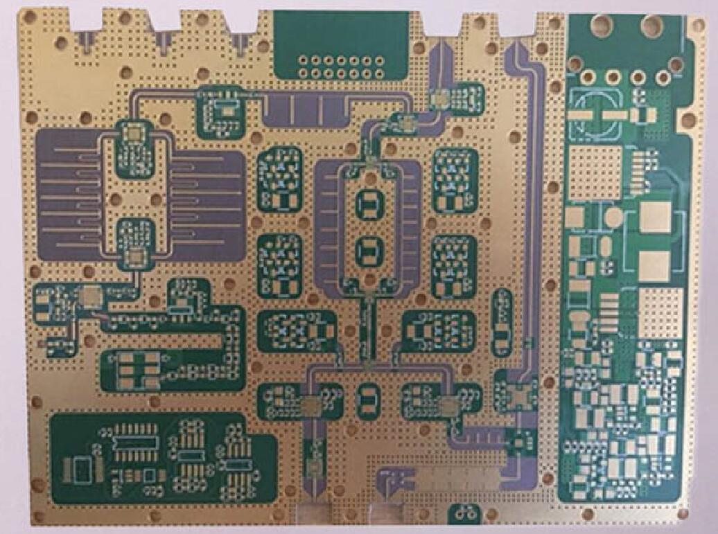
Benefits of the Rogers Printed Circuit Board
Printed circuit boards developed from the Rogers material have multiple benefits, and these include the following.
Rogers PCB possesses low moisture absorption and thermal expansion, besides solid dimensional stability under diverse conditions.
Rogers PCB material possesses high compatibility and simplicity in terms of fabrication because of its thinness (normally 0.1mm)
It also has exceptional thermal management, making it ideal for circuits and electronic elements or devices producing excess heat.
Another crucial feature that proves so useful entails reduced outgassing, especially in space applications.
The Rogers printed circuit board matches the trace dimensions and locations, consequently improving the impedance control.
Rogers’s printed circuit board offers a stable high-frequency performance
Characteristics of the high frequency Circuit board
1. The dielectric constant (Dk) must be small and stable, usually as small as possible. The signal transmission rate is inversely proportional to the square root of the material’s dielectric constant, and the high dielectric constant is liable to cause signal transmission delay.
2. The dielectric loss (Df) must be small. This mainly affects the quality of signal transmission. The smaller the dielectric loss, the smaller the signal loss.
3. The coefficient of thermal expansion of the copper foil is as uniform as possible. Because the inconsistency will cause the copper foil to separate during the cold and hot changes.
4. Low water absorption. High water absorption will affect the dielectric constant and dielectric loss during moisture.
5. Other heat resistance, chemical resistance, impact strength, peel strength, etc. must also be good
Then, what’s the advantage of high frequancy PCB?
The high-frequency circuit board with a small dielectric constant (DK) will be small, and the advanced sensing heating technology can achieve the demand for target heating, and the efficiency is very high. Of course, while paying attention to efficiency, it also has environmental protection characteristics, which is very suitable for the development direction of today's society.
The transmission speed is inversely proportional to the square root of the dielectric constant, which means that the smaller the dielectric constant, the faster the transmission speed. This is the advantage of high-frequency circuit boards. It uses special materials, which not only ensures the small characteristics of the dielectric constant, but also maintains stable operation. It is very important for signal conduction.
High-frequency circuit boards that are widely used in various industries for the demand for precision metal material heating treatment. In the process of their fields, not only can it be heated in different depth components, but also focuses on local characteristics. Concentration or decentralized heating method can be easily completed.
The constant and medium of the dielectric will have certain requirements for the environment, especially in the south. Wet weather will seriously affect the use of circuit board. The high-frequency circuit board made from very low water absorption materials can challenge this environment. At the same time, it also has the advantages of resisting the corrosion of chemical items. If you are still skeptical about incorporating high frequency PCBs in your electronics, you can always approach an industry expert in Hitech Circuits. The company has provided standard, as well as customized high frequency circuit boards to various industries.
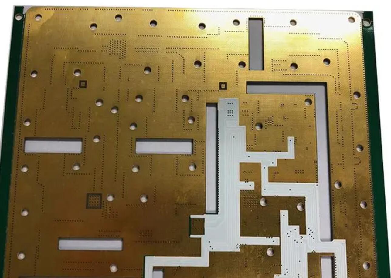
Types of Rogers PCB
RO3000
Rogers RO300 series are ceramic-filled PTFE composites and high-frequency circuit materials. Thus, they are useful for RF and microwave applications in commercial settings. In addition to the dielectric constant, the RO3000 PCB series have consistent mechanical properties. Thus, the multi-layer board design becomes easier. Besides, the dielectric constant for this Rogers PCB series is steady with the high temperature.
Advantages of the RO4000 series
Commercial laminates with the lowest loss available
Dk range from 3.0 to 10.2
Both with and without woven glass reinforcements
Low Z-axis CTE for improved plated through-hole reliability
RO4000
A Rogers RO4000 series prepreg and hydrocarbon ceramic laminate is an industry leader. Consequently, they are suitable for microwaves and millimeter-waves. Also, they use low-loss materials. It also provides circuit fabrication.
Advantages of RO3000 Series
The thermal conductivity of this series is above average (0.6-0.8).
It provides better microwave or RF performance.
It offers a wide range of DK, i.e., 2.55-6.15.
The production process is compatible with that of FR-4.
The low Z-axis CTE of this Rogers series provides a better option for through-hole technology.
Rogers 3003
It supports the 5G wireless application. Besides, this rogers PCB is suitable for automotive radar applications with a frequency of 77 GHz.
Rogers 3010
It provides affordable models along with advanced ceramic-filled PTFE materials. Thus, the stability of this Roger PCB delivers a better solution for broadband applications.
Rogers 3006
It provides stable electrical and mechanical properties. Besides, it provides dielectric constant across various ranges of temperatures.
Rogers 4350B
In addition to having a high dielectric constant (DK) control and low loss capabilities, Rogers 4350B material is ideal for high-power RF applications.
Rogers 4003
The Rogers 4003 model makes use of 1080 and 1674 glass fabric styles.
Rogers 4835
Despite significant oxidation resistance and increased temperatures, this 4835 laminate retains a high level of stability.
Rogers 4360G2
In terms of performance and processing capabilities, this laminate is perfect. In addition, the low-loss laminate contains ceramic thermostat materials filled with hydrocarbons.
Rogers PCB Material in Stock:
Rogers 4350B
Rogers 4003C
Rogers 3003
RT5880
RT5870
Lots of customers come to buy Rogers 4350B PCB. We keep All types Rogers 4350B material in stock, if you need any of them, welcome to contact us for the price and datasheet.
What are the Most Common Products of Rogers PCB?
The Rogers PCB product range is very wide. Information about all materials can be found on the official website of the company. We will focus only on microwave materials, which have long proven themselves in our market and are actively used in various microwave applications.
RO3000 and RO3200 – PTFE and ceramic based laminates
The RO3000 and RO3200 series were the first Rogers materials developed for general use in the early 1990s. They have excellent high frequency electrical properties and high thermal stability and can be used at frequencies up to 30-40 GHz. These laminates are widely used in automotive (collision avoidance systems), satellite communication systems, GPS and wireless antennas, and cable data networks.
Low coefficient of thermal expansion (CTE) along the Z-axis provides increased reliability of plated holes. CTE along the X and Y axes are close to the same value for copper and fiberglass (FR-4), which makes it possible to use these laminates both for the production of multilayer printed circuit boards and hybrid assemblies. The glass-reinforced RO3200 series has greater mechanical strength than RO3000.
The RO3000 Series Includes:
RO3003 (Dk 3.00; Df 0.0010)
RO3035 (Dk 3.50; Df 0.0015)
RO3006 (Dk 6.15; Df 0.0020)
RO3010 (Dk 10.2; Df 0.0022)
The RO3200 series is represented by materials:
RO3203 (Dk 3.02; Df 0.0016)
RO3206 (Dk 6.6; Df 0.0027)
RO3210 (Dk 10.8; Df 0.0027)
RO4000 – Heat-Resistant Materials with Added Ceramics, Glass Fiber Reinforced
RO4000 Series Microwave roger pcb materials have been developed to, on the one hand, provide high-quality microwave characteristics similar to those of PTFE-based materials, and, on the other hand, to make it compatible with traditional processing technology of reinforced PCBs (FR-4). RO4000 materials are glass fiber reinforced with a high glass transition temperature (Tg> 280 ° C) filled with thermosetting polymer with the addition of ceramics.
What is the Grading System of Rogers PCB Materials?
Unlike PTFE-based materials, RO4000 series materials do not require special chemical or plasma surface treatment in preparation for the production of plated vias. This makes the cost of manufacturing PCBs and mounting on RO4000 series microwave materials comparable to conventional epoxy laminates.
The most commonly used materials of this series: RO4003C and RO4350B – (Dk 3.38; Df 0.0027) and (Dk 3.48; Df 0.0037), respectively.
Special prepregs have been developed for these grades: RO4403C and RO4450B , which make it possible to create multilayer structures based on RO4003C and RO4350B materials, respectively. RO4403 prepreg has Dk 3.17 and Df 0.005, and refractory RO4450B prepreg has Dk 3.54 and Df 0.004. Like RO4000 materials, these prepregs are fully compatible with traditional FR4-based board technology.
What is the Function of RO4360G2 Series in Roger PCB Performance?
Another “advanced” material in this RO4360G2 series is heat-resistant, has an excellent thermal conductivity of 0.81 W / m / K, low CTE along the Z-axis, which increases the reliability of plated holes and simplifies drilling processes. It has Dk 6.15, is used in the manufacture of microwave electronics and allows operation at frequencies of 4 GHz. RO4360G2 is FR-4 compatible and offers the same reliability and consistency as RO4350B.
Laminates RO4835 (Dk 3.48, Df 0.0037@10GHf) and high frequency version RO4835T (Dk 3.33, Df 0.0030@10GHf) have been developed as an improved version of RO4350B. They have better stability at elevated temperatures and improved oxidation stability (10 times better than RO4350B).
Manufactured in the same configurations and thicknesses as the RO4350B and are IPC-4103 compliant. Applications: automotive radars and sensors, power amplifiers, phased array radars, RF components.
One of the company’s recent advances is the RO4000 LoPro laminate , which offers 10% lower insertion loss than the standard RO4000 series. Basically, these laminates are used in antenna systems, radars, digital data transmission rogers pcb systems, as well as for the production of microwave components (especially power amplifiers).
RT / duroid6000 – PTFE Ceramic Laminates
There are several varieties of this type of material. Laminates RT / duroid6002 (Dk 2.94; Df 0.0012) and RT / duroid6202 (Dk 2.9; Df 0.0015) were developed in the late 1980s to address some of the shortcomings of PTFE-based materials.
The exceptional properties of these materials are the high stability of the dielectric constant in a wide temperature range and the coefficient of thermal expansion, which almost coincides with the CTE of roger pcb copper. All this makes these materials ideal for the manufacture of sandwich structures used in aerospace equipment subject to sudden changes in temperature, where there are strict requirements for the reliability of plated vias, and also requires low dielectric losses.
Ceramic Laminates for Rogers PCB
This class also includes materials RT / duroid6006 and RT / duroid6010LM – ceramic PTFE laminates. The materials RT / duroid6006 (Dk 6.15; Df 0.0027) and 6010LM (Dk 10.2; Df 0.0023) were developed in the late 1970s with the aim of reducing the overall dimensions of printed circuit boards, since the high dielectric constant allows for smaller devices.
Thermal conductivity of RT / duroid 6035HTC laminate (Dk 3.5; Df 0.0013) is 2.4 times higher than that of standard RT / Duroid 6000 series models. Electrolytic foil, treated on the smooth side, which is resistant to high temperatures, allows the use of such laminate for high power amplifiers, combiners, power dividers, couplers and filters.
Thermal Testing of Microwave Boards
Results of thermal testing of a roger printed circuit board
Printed circuit board with copper base;
PCB material – Rogers;
The board is connected to the base using pressure glue;
Base thickness – 3 mm.
Test conditions and procedure:
Verification was carried out in accordance with standard tests for in-house manufactured instruments.
The thermal chamber is programmed for 3 cycles (1 cycle: -60 ° С… + 85 ° С with exposure for 30 minutes at each temperature). After 3 cycles, visual control was carried out using an MBS-10 microscope at a magnification of 16 × and 32 ×.
30 thermal cycles were carried out.
During the tests, no cracks, no delamination, no violations of the glue seam were revealed. A slight change in the color of the glue was observed (this is possible because the test sample was in a leaky volume). Conclusions based on the test results: the sample of the product corresponds to the declared properties in terms of the quality of the glue line.
How to Increase the Integration of Microcircuits of Roger PCB?
Multilayer rogers PCB has been designed to simplify and optimize the wiring of double-sided dielectric plates. The increase in the integration of microcircuits, the provision of a significant number of interlayer connections, as well as the introduction of packages with a large number of pins – all this became the primary reason for the creation and intensive development of MPP technologies.
As the roger pcb models and technological requirements become more complex, not only the quality has increased, but also the total number of layers. As a result, sophisticated multilayer printed circuit boards can have 30-32 layers.
Features of Use
MPP are used in high-frequency devices with a regulated impedance of signal circuits and an acceptable level of electromagnetic interference.
WFP Materials
Among the main materials of multilayer rogers pcb boards are:
Rogers Ro4003 and Ro4350 series.
Glass fiber laminates FR4 prepreg
Combination is possible among base materials. For example: use in flexible-rigid printed circuit boards polyimide (PI) with FR-4 fiberglass.
Design
The design is based on alternating thin dielectric layers combined with topology elements. When creating, the layers are connected into a single, integral multi-layer board.
Electrical connections, depending on the pressing technique, can have both through-type vias and interlayer vias:
Outer layers to inner layers – blind vias;
Inner layers are buried vias.
Any multilayer PCB construction consists of 2 elements:
Cores– core – a dielectric layer of considerable thickness foiled on both sides.
Preprega– prepreg – dielectric foil-clad on one side or not foil-clad layer of small thickness. It acts as a connecting internuclear layer.
Layer Classification of Multilayer Roger PCB
Outlayer
Another name is editing. The essence of the layer: the installation of components and the organization of connections between located in the immediate vicinity of the board elements
Power layers
Presented in the form of solid polygons. They have minimal current resistance and low induction. Contributes to the shielding of signal layers.
Signal
You can create connections between electronic components. Feature: significant indicators of the density of communication lines
Heat-conducting
Excess heat of circuit components with increased technological values of heat release is removed and distributed
Production methods
Layer-by-layer building.
Pairwise pressing.
Combination of methods.
The main method is considered to be the method of pairwise pressing of nuclear blanks – thin double-sided boards of a certain topology. The method is implemented using cushioning glass fabric. Layer-by-layer build-up / metallization of core holes (through type) occur by a subtractive chemical method. Photoresists are used as a protective coating.
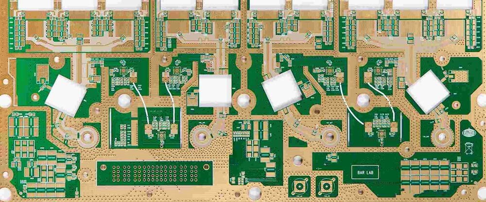
Rogers Printed Circuit Board
We all hear about Rogers PCB, but very few of us understand what it is. So what does it all entail? The term Rogers implies a manufacturing company that produces the laminate material deployed in the fabrication of printed circuit boards. The material comes as an FR-4 core, complete with a copper laminate. Consequently, this material gets referred to as Rogers FR4.
It is also prudent to know that the core materials from Rogers have an established reputation when it comes to better high-frequency properties. While more expensive, Rogers PCB laminates (fr4) prove less loss under high frequencies, making them perfect as RF circuit boards. At this moment, you might wonder if there is a difference between Rogers PCB material and an FR-4 material. So is there a distinction?
Yes, a distinction exists between a Rogers PCB material and an FR-4 material, as much as the Rogers material contains an FR-4 in its core. Below, some of the most notable differences between the two PCB materials.
Difference Between Rogers Materials and FR-4 Materials
By combining Rogers PCB layers with FR-4 layers, we can achieve reduced cost and maximum performance compared to if we used only Rogers layers. Thus, this process should use Rogers PCB cores instead of prepregs for this process.
FR-4 stack up with 6 layers is shown below. Because prepreg is less expensive than cores, it is placed on the outside to minimize cost. A foil build is often referred to as this.
Rogers layers are required on the outside layers, but the core is usually found on the layers that need them. Below is an example with 6 layers but with 3 cores instead of 2. This configuration is sometimes called a "core build" or "cap construction" board. Rogers PCB is a high-frequency circuit board that has ceramic laminates and reinforced hydrocarbon. A Rogers PCB may be made from cores and prepregs, but most often, the top two copper layers are carried on the core, while the rest of the board is made from standard FR-4 to reduce the cost. The PCB materials absorb the signal, due to which it has less signal loss compared to that of FR-4. At higher frequencies, the signal loss is greater in FR-4 materials. This is also the signal length and design dependent.
High-Frequency
PCB with FR-4 materials is preferred due to their low cost, reliability, and well-understood electrical and mechanical properties. They are used in various applications ranging from microwave designs to audio circuits. Unfortunately, FR-4 printed circuit boards are not suitable for high-frequency applications. Rogers created the most well-known high-frequency-special laminates. Its materials have a constant dielectric reduction of close to 20% when compared to FR-4 printed circuit boards.
The best way to determine whether your project will benefit from high-frequency laminates is to assess electrical and mechanical requirements. If you find both variations are too broad, Rogers PCB material is a better option.
Dissipation
The material used is most important when producing printed circuit boards, though it may require a high cost. However, it is not the only issue that knows the content value when it comes to the loss factor or Df. FR-4 printed circuit boards will be affected or reduced. The losses are greater when compared to printed circuit boards made from Rogers materials.
In other words, when compared to Rogers PCB, FR-4 materials have a higher dissipation factor, especially at high frequencies. Typical values for FR-4 printed circuit boards are around 0.020 and close to 0.004 for Rogers boards. Dissipation of FR-4 materials increases with frequency. High-frequency laminates primarily have a frequency-dependent stable dissipation characteristic.
The signal loss is minimized with the lower dissipation factor in FR-4. Also, the automated assembly process and the processing of FR-4 materials make them easier in the assembly and manufacturing process.
Impedance Stability
Impedance is the measure of the current opposition when applying voltage. In many design applications, the stable impedance is essential and is an area where the materials like Rogers and FR-4 are applied.
FR-4, despite its low cost, is prone to high variations in the dielectric constant with the change in temperature across the length and width of the substrate. In terms of impedance stability, Rogers' material has a wider range of dielectric constants than FR-4 content.
High-frequency laminates are preferable for circuits that require little variation over wide temperature ranges. In this case, you may need to use printed circuit boards made of Rogers materials rather than FR-4 materials, especially if most of your operations involve working in high-temperature environments.
Dielectric Constant
The dielectric constant of any material measures a substance's ability to store some electrical energy across an electrical field. When it comes to dielectric constant, FR-4 has a dielectric constant of about 4.5, which is much lower than Roger's material, which has a dielectric constant of about 6.15 to 11.
The dielectric constant of FR-4 is comparatively higher than that of plastic materials. Using FR-4 materials can save at least 25% of PCB made from such materials. Other factors that make FR-4 articles available include their lightweight, moisture resistance, and high dielectric strength. Even though the Rogers PCB has a higher dielectric than FR-4, you can go with FR-4. FR-4 and Rogers 4350b and 4350 are similar manufacturing processes, although FR-4 stores electrical energy effectively.
Thus, PCB with higher dialect trends breaks easier when subjected to intense electric fields.
Space Application
Space exploration has recently increased, with many countries attempting to send people into space. When it comes to space applications, the materials used in the production of printed circuit boards are very important.
Some materials may not perform as expected. FR-4 and Rogers are two very different materials regarding their applicability or use in space. Outgassing occurs in space. Outgassing occurs when trapped gases in powder coating are released during the curing process. Corrosive materials or moisture can penetrate the surface through the pinholes and destroy some parts.
Although FR-4 materials provide an excellent balance of electrical stability, durability, cost, and manufacturability, Rogers materials are considered some of the best in space applications. In short, they are low outgassing and suitable for almost any type of space exploration or use.
Temperature Management
A wide range of electrical devices requires heat management materials. Because the temperature of these products maintains at specific levels, thermal management materials are required when designing PCBs. The thermal coefficient of the dielectric constant is used to characterize or gauge printed circuit board materials. This is nearly 200 ppm per degree Celsius change for FR-4 materials. Although a small number, it can cause significant temperature variations.
The working condition of little variation over the higher temperature is better for working with Rogers material. Thus, we can say that Rogers material performs better in temperature management. Therefore, Rogers materials, a high 0-frequency thermoset, are more robust and excellent for higher temperatures.
Difference between Rogers PCB and Ceramic PCB
Rogers PCB has no ceramic powder, whereas Ceramic PCB has ceramic power that is heat conducting.
Rogers PCB has a copper foil base, whereas ceramic PCB has a ceramic base.
Rogers PCB is costlier than Ceramic PCB.
Rogers PCB vs RF PCB
RF PCB is a more complex PCB type compared to Rogers PCB.
The operating frequency of RF PCB is 100MHz to 2GHz, whereas Rogers PCB has an operating frequency of 6 GHz.
Rogers PCB vs Teflon PCB
Teflon PCB operates at a frequency of 5GHz, whereas Rogers PCB operates at a 6GHz.
Teflon PCB works for low-cost applications, whereasRogers PCB works for high-cost PCB applications.
Conclusion
Choosing the appropriate material for your printed circuit board is a crucial decision that will impact its suitability for specific applications. Through this blog post, we aim to enhance your understanding of Rogers PCBs. If you require further information or guidance on selecting the most suitable PCB for your project, please don’t hesitate to contact us. Hitech Circuits is a leading PCB manufacturer in
At Hitech Circuits, we have our expertise and engineers who work with our clients from the beginning of the project and provide the stacks ups, designs, and materials for the manufacturing and assembling. Hitechpcb is the leading manufacturer that fulfills all your PCB manufacturing requirements and needs. You can contact us anytime, and feel free to ask any questions and learn about your PCB requirements.

0086-755-29970700
sales@hitechpcb.com; sales@hitechcircuits.com
2F, Building C, Suojia Technology Park, Hangcheng, Bao’an, Shenzhen, Guangdong, China 518126
 Chinese
 English
 Russian
 Spanish
 Portuguese


